TB-D5008-INV-001 G.M. International s.r.l.
GM International

TB-D5008-INV-001
Termination Board 8 positions for Invensys FBM200 with I/O cards: Analog In FBM211 and Digital In FBM207b/c

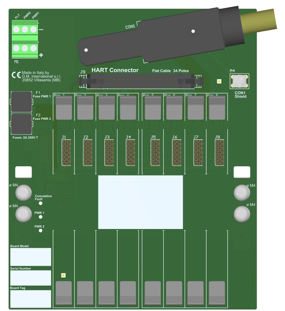
This Termination Board (TB) provides direct connection between the I/O Card of the system and D5000 / D6000 Series modules. The Intrinsically Safe protection and signal isolation between Safe and Hazardous Area, is provided by D5000 Series Associated Apparatus. The 24 Vdc Power Supply of the TB is connected to two plug-in terminal blocks, for a redundant power supply. The power supply for modules is given by TB power bus.

FEATURES

  • AI card type FBM211, 16 channels Analog Input board interface.
  • DI card type FBM207b/c, 16 channels Digital Input board interface.
  • 8 position Terminal Board for up to 16 channels.
  • Lower cables installation and maintenance costs.
  • Power supplies fault monitoring.
  • Spare fuse provided.
  • Mounting hardware provided for: Wall mounting, M4 thread screw; Wall mounting, M4 self tapping screw; Single Din Rail mounting kit.

STATUS

 
   ACTIVE
Product lifecycle policy (EN)

CHANNELS

16

Request a free and personalized quotation!

Technical Data


Supply

Type 24 Vdc nom (20 to 30 Vdc) reverse polarity protected, double terminal blocks for redundant power supply, with OR diodes to mix supply voltages.
Connection by polarized plug-in disconnect screw terminal blocks to accommodate terminations up to 2.5 mm2.
2 LEDs indication green color, one for supply 1 and one for supply 2.
Protection fuse 2 A time lag (spare fuse provided on Termination Board).

Fault detection

Preventive - abnormal supply voltage supply 1 or supply 2 is < 18 Vdc (Under Voltage, UV) or > 30 Vdc (Over Voltage, OV).
Critical - abnormal supply voltages or cumulative fault both supplies are in under (< 18 Vdc) or over (> 30 Vdc) voltage condition OR cumulative fault indication (about presence of short or open field circuit for any DO channel).
LED fault signaling (for both case 1 and 2) 2 red LEDs (UV and OV of supply 1); 2 red LEDs (UV and OV of supply 2); a cumulative fault red LED.
Relay fault signaling (one for each case 1 or 2) a voltage free NE SPDT - 1 Form C relay contacts (de-energized in fault condition)
Connection by polarized plug-in disconnect screw terminal blocks to accommodate terminations up to 2.5 mm2.
Contact rating 2 A 36 Vac 72 VA, 2 A 48 Vdc 80 W (resistive load).

FBM200 I/O card interface

Connection SUB D 37 poles male connector (requires female mating connector).

HART Multiplexing

Connection 34 poles male connector (requires female mating connector).

Environmental conditions

Operating temperature temperature limits – 40 to + 70 °C, relative humidity max 90 % non condensing, up to 35 °C.
Storage temperature temperature limits – 45 to + 80 °C.

Mounting

Type Hardware included for mounting on wall and single DIN rail.
Weight about 200 g (excluding modules and mounting options).
Location Safe Area / Ordinary locations.
Dimensions Width 165 mm, Depth 185 mm, Height 125 mm.

Data Sheet


Schneider Foxboro TB Summary ( EN | FR | JA | CN | PT | IT | ES | DE )

Certifications


Type Description Area Number Issued by Issue Date
EMC 5700 and TB EAC EMC Declaration of Conformity ( RU ) Eurasian Community ЕАЭС N RU Д-IT.АЖ38.В.00125/19 EUROCERT 2019-05-30

Declarations of Conformity


EU Declaration of Conformity for RoHS, ASBESTOS. ( EN )
EU Declaration Termination Boards TB, TBE, TUE ( EN )
Declaration of Conformity G3 compliance ( EN )

Dimensions