D1044D G.M. International s.r.l.
GM International

D1044D
SIL 2 - SIL 3 Digital Relay Output Loop / Bus Powered DIN-Rail

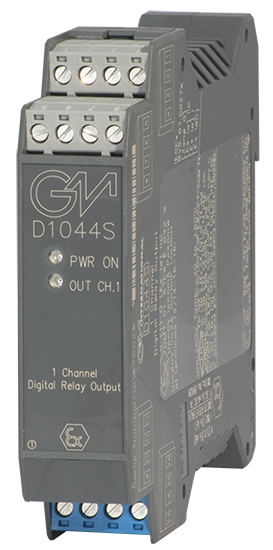
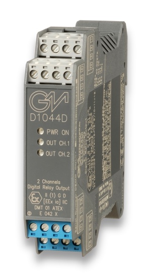
The single and dual channel DIN Rail Digital Relay Output, D1044S and D1044D, are digital output modules enabling a Safe Area contact, logic level or drive signal, to control a device in Hazardous Area, providing 3 port isolation (input/output/supply). Outputs are galvanically isolated and inputs are depolarized to ease wiring operations. Typical applications include switching of Hazardous Area circuits, changing of polarities and sounder tones, calibrating of strain gauge bridges, resetting of field devices, testing of fire detectors. Each input channel can be isolated from supply (Bus Powered mode) or externally connected (by wiring) to supply (Loop Powered mode, where the safety PLC directly supplies the module and its input channel). Each output channel provides a SPDT relay, with two contacts defined NO (Normally Open) and NC (Normally Close) when the output relay is de-energized. Considering each channel NE (Normally Energized), the output relay is energized,so that NO contact is closed (useful for NE loads or Hazardous Area circuits) and NC contact is open (useful for ND loads or Hazardous Area circuits). The safe state is reached when the channel and the output relay are de-energized, so that NO contact is open (de-energizing loads or Hazardous Area circuits) and NC contact is closed (energizing loads or Hazardous Area circuits).

FEATURES

  • SIL2 /SIL3/SC3
  • Input from Zone 0 (Zone 20), Division 1, installation in Zone 2, Division 2.
  • High Density,two channels per unit.
  • Voltage, contact, logic level input.
  • Two SPDT Relay Output Signals.
  • Three port isolation, Input/Output/Supply.
  • EMC Compatibility to EN61000-6-2, EN61000-6-4, EN61326-1.
  • 250 Vrms (Um) max. voltage allowed to the Instruments associated with the barrier.

STATUS

 
   PHASE-OUT
Next: SPARE-ONLY (2027-01-01)

Product lifecycle policy (EN)

ALTERNATIVE PRODUCT

CHANNELS

2

Request a free and personalized quotation!

Technical Data


Supply

Voltage 24 Vdc nom (20 to 30 Vdc) reverse polarity protected, ripple within voltage limits ≤ 5 Vpp.
Current Consumption 55 mA with relays energized.
Power Dissipation 1.35 W with 24 V supply voltage and relays energized.
Max. power consumption at 30 V supply voltage and relays energized, 1.5 W

Input

Type switch contact, logic level.
Trip voltage levels OFF status ≤ 1.0 V, ON status ≥ 6.0 V (maximum 30 V).
Current Consumption 3 mA @ 24 V(≈ 10 KΩ input impedance).

Output

Type voltage free SPDT relay contact.
Contact material AgNi90/10.
Contact rating 60 Vdc, 2 A for use in Intrinsic Safety applications, 2 A 250 Vac 500 VA, 2 A 250 Vdc 80 W (resistive load) for non Intrinsic Safety applications.
DC Load breaking capacity 15 * 106 / 1 * 105 operation, typical.
Mechanical / electrical life see innstruction manual
Operate / release time 5 / 2 ms typical.
Bounce time NO / NC contact 1 / 5 ms.
Response time 20 ms.
Frequency response 10 Hz maximum.

Isolation

Test Voltage I.S. Out/In 1.5 KV; I.S. Out/Supply 1.5 KV; I.S. Out/I.S. Out 500 V; In/Supply 500 V; In/In 500 V.

Environmental conditions

Operating temperature limits -20 to + 60 °C, relative humidity max 95 %.
Storage temperature limits -45 to + 80 °C.

Safety description

Safety parameters Uo/Voc = 0 V, Io/Isc = 0 mA, Po/Po = 0 mW at terminals 13/14-15-16, 9/10-11-12 (Uo, Io, Po equal to the connected Intrinsic Safety circuit). Ui/Vmax = 60 V, Ii/Imax = 2 A, Ci = 0 nF, Li = 0 nH at term. 13/14-15-16, 9/10-11-12. Um = 250 Vrms, -20 °C ≤ Ta ≤ 60 °C.

Mounting

Type EN/IEC60715 TH 35 DIN-Rail.
Weight about 140 g
Connection by polarized plug-in disconnect screw terminal blocks to accomodate terminations up to 2.5 mm2.
Location Safe Area/Non Hazardous Locations or Zone 2, Group IIC T4, Class I, Division 2, Groups A, B, C, D Temperature Code T4 and Class I, Zone 2, Group IIC, IIB, IIA T4 installation.
Protection class IP 20.
Dimensions Width 22.5 mm, Depth 99 mm, Height 114.5 mm.

Data Sheet


Datasheet of D1044 ( EN )
D1000 Series Common Specifications and Dimensional Drawing ( EN )

Instruction Manual


Instruction Manual D1044 ( EN )
Instruction Manual D1000 Series ( EN | RU )
Ex safety instruction manual for D1000 series ( EN | IT )
INMETRO safety instruction manual for D1000 series ( PT )

Certifications


Type Description Area Number Issued by Issue Date
ATEX DEKRA ATEX D1000 Series English Certificate ( EN ) Europe DMT 01 ATEX E 042 X DEKRA 2022-04-25
ATEX IMQ Zone 2 Applications D1000 Series Certificate ( EN ) Europe IMQ 09 ATEX 013 X IMQ 2022-05-03
EMC D1000 EAC EMC Declaration of Conformity ( RU ) Eurasian Community ЕАЭС N RU Д-IT.НХ37.В.06311/20 EUROCERT 2020-08-13
Ex EAC Ex Certificate for D1000 Series ( RU ) Eurasian Community ЕАЭС RU С-IT.НА67.В.00113/20 TECHNOPROGRESS 2020-09-04
Ex FM No.3024643-3029921C Certificate ( EN ) North America 3024643-3029921C FM 2005-12-16
Ex INMETRO Certificate DNV 13.0108 X for D1000 series ( EN ) Brazil DNV 13.0108 X DNV 2022-12-10
FSM TUV IT 22 SIL 0093 Functional Safety Certificate ( EN ) International TUV IT 22 SIL 0093 TUV_SUD 2022-07-25
IECEx IMQ IECEx Zone 2 Applications D1000 Series Certificate ( EN ) International IECEx IMQ 13.0011X IMQ 2022-05-03
IECEx DEKRA IECEx for D1000 Series ( EN ) International IECEx BVS 07.0027X DEKRA 2022-05-30
Maritime KR Maritime Certificate D1000 Series ( EN ) International MIL20769-EL001 KR 2022-07-04
SIL TUV C-IS-236198-04 SIL Certificate Summary ( EN ) International C-IS-236198-04 TUV_SUD 2022-10-14

Declarations of Conformity


EU Declaration of Conformity D1000 series ( EN | IT )
EU Declaration of Conformity for D1000 series (zone 2) ( EN | IT )
EU Declaration of Conformity for RoHS, ASBESTOS. ( EN )
Declaration of G3 compliance for D1000_PSD1000-PSD1001-PSD1001C-PSD1004-PSD1220-PSD1220-098 SERIES ( EN )

Dimensions


Image of D1044S-D1044D_size

Connections


Drawings


2d_drawing_D1000_dwg ( EN )
3d_drawing_D1000_dwg ( EN )
3d_drawing_D1000_stp ( EN )

RELATED PRODUCTS