D1064S G.M. International s.r.l.
GM International

D1064S
SIL 2 Load Cell/Strain Gauge Bridge Isolating Converter DIN-Rail
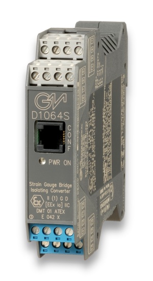
 Model D1064S

The single channel DIN Rail Load Cell/Strain Gauge Bridge Isolating Converter D1064S acts as a galvanically isolated interface installed between a PLC/DCS in Safe Area and a load cell (or group of load cells) in Hazardous Area. Up to four 350 Ω load cells, or five 450 Ω load cells, or ten 1000 Ω load cells can be connected in parallel. It provides a fully floating power supply voltage with remote sensing capabilities to load cells located in Hazardous Area and converts the mV signal from the load cell into a 0/4-20 mA or 0/1-5 V or 0/2-10 V signal according to user desired range. Output circuit provides both current source and sink capabilities. Modbus output is also provided to interface PLC/DCS using digital communication.

FEATURES

  • SIL2/SC2
  • Input from Zone 0 (Zone 20), Division 1, installation in Zone 2, Division 2.
  • Strain Gauge Bridge Isolated Converter.
  • Up to four 350 Ω load cells in parallel or up to five 450 Ω load cells in parallel or up to ten 1000 Ω load cells in parallel.
  • 0/4-20 mA, 0/1-5 V, 0/2-10 V Output Signal.
  • Modbus Output.
  • Field Automatic Calibration
  • Three port isolation, Input/Output/Supply.
  • EMC Compatibility to EN61000-6-2, EN61000-6-4, EN61326-1.
  • Fully programmable operating parameters.
  • 250 Vrms (Um) max. voltage allowed to the Instruments associated with the barrier.

STATUS

 
   PHASE-OUT
Next: SPARE-ONLY (2027-01-01)

Product lifecycle policy (EN)

ALTERNATIVE PRODUCT

CHANNELS

1

Request a free and personalized quotation!

Technical Data


Supply

Voltage 24 Vdc nom (20 to 30 Vdc) reverse polarity protected, ripple within voltage limits ≤ 5 Vpp.
Current Consumption 70 mA with four 350 Ω load cells connected and with 20 mA output typical.
Power Dissipation 1.4 W with 24 V supply voltage, four 350 Ω load cells connected and 20 mA output typical.
Max. power consumption at 30 V supply voltage, short circuit input, overload condition and PPC1090 connected, 2.2 W.

Input

Type up to four 350 Ω load cells (parallel connection). up to five 450 Ω load cells (parallel connection). up to ten 1000 Ω load cells (parallel connection).
A/D Conversion time 100 ms.
Bridge supply voltage 4.2 V nominal.
Bridge output signal 1 to 4 mV/V.
Line resistance compensation ≤ 10 Ω.

Output

Type 0/4 to 20 mA, on max. 600 Ω load in source mode; V min. 5 V at 0 Ω load V max. 30 V in sink mode, current limited at 22 mA or 0/1 to 5 V or 0/2 to 10 V signal, limited at 11 V.
Resolution 1 μA current output or 1 mV voltage output.
Response time ≤ 50 ms (10 to 90 % step change).
Output ripple ≤ 20 mVrms on 250 Ω load.

Modbus Output

Type Modbus RTU protocol up to 115.200 baud.

Input performance

Type Ref. Conditions 24 V supply, 250 Ω load, 23 ± 1 °C ambient temperature.
Accuracy after autocalibration ≤ ± 0.05 % of full scale.
Linearity accuracy ≤ ± 0.02 % of full scale of input range.
Temperature influence ≤ ± 0.002 % of full scale of input range for a 1 °C change.
Supply voltage influence ≤ ± 0.002 % of full scale of input range for a min to max supply voltage change.

Analog output performance

Type Ref. Conditions 24 V supply, 250 Ω load, 23 ± 1 °C ambient temperature.
Calibration accuracy ≤ ± 0.05 % of full scale.
Linearity error ≤ ± 0.05 % of full scale.
Supply voltage influence ≤ ± 0.02 % of full scale for a min to max supply change.
Load influence ≤ ± 0.02 % of full scale for a 0 to 100 % load resistance change.
Temperature influence ≤ ± 0.01 % on zero and span for a 1 °C change.

Isolation

Test Voltage I.S. In/Out 1.5 KV; I.S. In/Modbus Out 1.5 KV; I.S. In/Supply 1.5 KV; Out/Supply 500 V; Modbus Out/Supply 500 V; Out/Modbus Out 500 V.

Environmental conditions

Operating temperature limits –20 to + 60 °C, relative humidity max 90 % non condensing, up to 35 °C.
Storage temperature limits – 45 to + 80 °C.

Safety description

Safety parameters Uo/Voc = 5.9 V, Io/Isc = 196 mA, Po/Po = 576 mW at terminals 9-10-11-12-13-14. Um = 250 Vrms, -20 °C ≤ Ta ≤ 60°C.

Mounting

Type EN/IEC60715 TH 35 DIN-Rail.
Weight about 155 g.
Connection by polarized plug-in disconnect screw terminal blocks to accomodate terminations up to 2.5 mm2.
Location Safe Area/Non Hazardous Locations or Zone 2, Group IIC T4, Class I, Division 2, Groups A, B, C, D Temperature Code T4 and Class I, Zone 2, Group IIC, IIB, IIA T4 installation.
Protection class IP 20
Dimensions Width 22.5 mm, Depth 99 mm, Height 114.5

Data Sheet


Datasheet of D1064 ( EN )
D1000 Series Common Specifications and Dimensional Drawing ( EN )

Instruction Manual


Instruction Manual D1064 ( EN )
Instruction Manual D1000 Series ( EN | RU )
Safety Manual D1064 ( EN )
Ex safety instruction manual for D1000 series ( EN | IT )
INMETRO safety instruction manual for D1000 series ( PT )

Certifications


Type Description Area Number Issued by Issue Date
ATEX DEKRA ATEX D1000 Series English Certificate ( EN ) Europe DMT 01 ATEX E 042 X DEKRA 2022-04-25
ATEX IMQ Zone 2 Applications D1000 Series Certificate ( EN ) Europe IMQ 09 ATEX 013 X IMQ 2022-05-03
EMC D1000 EAC EMC Declaration of Conformity ( RU ) Eurasian Community ЕАЭС N RU Д-IT.НХ37.В.06311/20 EUROCERT 2020-08-13
Ex EAC Ex Certificate for D1000 Series ( RU ) Eurasian Community ЕАЭС RU С-IT.НА67.В.00113/20 TECHNOPROGRESS 2020-09-04
Ex FM No.3024643-3029921C Certificate ( EN ) North America 3024643-3029921C FM 2005-12-16
Ex INMETRO Certificate DNV 13.0108 X for D1000 series ( EN ) Brazil DNV 13.0108 X DNV 2022-12-10
FSM TUV IT 22 SIL 0093 Functional Safety Certificate ( EN ) International TUV IT 22 SIL 0093 TUV_SUD 2022-07-25
IECEx IMQ IECEx Zone 2 Applications D1000 Series Certificate ( EN ) International IECEx IMQ 13.0011X IMQ 2022-05-03
IECEx DEKRA IECEx for D1000 Series ( EN ) International IECEx BVS 07.0027X DEKRA 2022-05-30
Maritime KR Maritime Certificate D1000 Series ( EN ) International MIL20769-EL001 KR 2022-07-04
Metrological Metrological Certificate Russia for D1000 Series ( RU ) Russia 64283-11 ROSSTANDART 2021-03-10
SIL TUV C-IS-722238330 SIL Declaration of Compliance Summary ( EN ) International C-IS-722238330 TUV_SUD 2024-01-19

Declarations of Conformity


EU Declaration of Conformity D1000 series ( EN | IT )
EU Declaration of Conformity for D1000 series (zone 2) ( EN | IT )
EU Declaration of Conformity for RoHS, ASBESTOS. ( EN )
Declaration of G3 compliance for D1000_PSD1000-PSD1001-PSD1001C-PSD1004-PSD1220-PSD1220-098 SERIES ( EN )

Dimensions


Image of D1064S_size

Connections


Software


SWC1090-D1000 Software Configurator for Windows ( EN )
Instruction Manual SWC1090 ( EN )